Natural Secured Menus Architecture
Functional Specifications
Revision 2
September 25, 1992
University of Arkansas, Fayetteville
Computing Services
Kathryn Cantrell
W. David Wimberly
Introduction
NSM
Concepts
System
Definition
Standards
Additional
Considerations
Figures
- Sample menu
screen
- Sample menu banner
with parameter
- Sample function module
banner with parameter
- Processing Flow of an
NSM Application
The Natural Secured Menus Architecture (NSM-A) is both an
approach for designing and developing online Natural applications
and a collection of tools and facilities to assist in that
endeavor. It has been designed to provide:
- A common user interface for Natural applications.
- Central facilities for menu presentation, navigation, and
command processing
- Security features needed by most applications.
- Maintenance facilities that allow individuals responsible for
an application the ability to administer the security for their
system directly and independently.
- Standards and models for developing sophisticated and feature
rich on-line application programs (also known as function
modules within NSM).
The NSM Architecture also provides a high level of commonality
between applications so that training requirements of individuals
who use or maintain multiple NSM applications is reduced
significantly.
These Functional Specifications were prepared in order to
provide a clear and concise definition of the NSM Architecture.
This document is intended to provide all the information
necessary for an individual to develop an application using this
architecture. The UAF Program Generator functional specifications
should also be consulted since that facility automates the
creation of most program code for an NSM application.
Additionally, portions of this documentation will assist
individuals in using applications that have been developed in the
NSM Architecture.
These specifications were first prepared and released on November
15, 1988. Revision 1 was prepared November 22, 1989 to
incorporate text prepared for the presentation of the NSM
Architecture at the Fifth Annual SAG University/College BIG
Conference. In September of 1992, Revision 2 was prepared to
include significant enhancements that were made to the NSM
Architecture, prompting reference to the revised system as
NSM v2 (version 2). In January 2001 this
documentation was converted to HTML with some editing and updates
performed at that time.
Features of the NSM Architecture include:
- Use of a Command-Driven, Menu-Augmented (CDMA) interface so
that applications will be "self-teaching, confidence-building,
and task-efficient". This approach accommodates the needs of the
new or infrequent user as well as the expert user. Please refer
to the article "Command-Driven Application Architecture" by John
B. Wheat, Third Annual University/Software AG BIG Users's Group
Conference for additional information on CDMA systems.
- Increased productivity during system development due to a
defined and tested online user interface and the existence of a
code generator that accommodates most processing needs. The
generated programs can be regenerated to incorporate subsequent
enhancements.
- Implementation of a common user interface across multiple
applications. NSM-A applications will look and operate similarly,
thus reducing the training time of individuals who use them.
- Provision for command level security so that a user or group
of users can be restricted from one or more commands within an
application. Those restricted commands are suppressed from the
user's menus.
- Assignment of a security level to an individual user within
an application. Each application defines the actions a security
level allows, and the evaluation of a user's security level is
done through common code in each function module. Additionally,
more restrictive security levels may be assigned to a user for
selected commands through the use of command security
groups.
- Assignment of record level restrictions (security by value)
to a user or group of users. These restrictions are passed to
each function module for interpretation, resulting in limited
access to data.
- Allowance for the security administration of the application
to be performed by an end user who has been designated as an
application owner. This facility is provided by the NSM
Maintenance System and is possible due to the data based
nature of the NSM architecture.
- An application notice facility where messages and other
general communications can be posted. A user will receive each
notice only once.
- Provision for a temporary lock so that all users or selected
groups of users are temporarily prevented from accessing an
application. An explanation of the reason for the lock must be
included.
- The ability to suspend a function in the middle of an action,
go to another function and complete some other unrelated action,
and then return to the original function. Three active levels are
permitted.
- Display of a warning if modifications have been made on a
screen and the user's input would result in losing those changes
before they have been saved.
- The capability for a function to use multiple screens (up to
4). PF keys may be used to scroll between screens, or the user
may specifically request a screen number.
- Automatic determination of the validity of each screen in
a function. The user is prompted to enter data, press PF10, or go
to a specific screen number to validate data there.
- A "Next Record" function whereby the next logical record is
retrieved from the data base and displayed.
- A Copy action that will copy predetermined fields to effect
either an add or an update to the specified key.
- Color and attribute settings for fields on the screen derived
from user specified options (maintained as part of a user
profile).
- Standardization of common PF Keys across all NSM
applications.
- A central data resource of information regarding users and
applications is provided. The NSM Architecture files may be used
by other applications for other purposes and may be expanded to
include additional data elements needed by those applications
(e.g. the parameters of the user profile).
- Implementation of these features without adversely affecting
system performance. This is made possible by the extensive use of
the global data area for storing and sharing information between
programs.
The University of Arkansas acquired Natural and other Software
AG products in the Summer of 1986. The first Natural applications
developed used their own approach to menu design and relied upon
the security features of Natural Security. Through the Third
Annual SAG University/College BIG User's Group Conference, UAF
was exposed to John Wheat of the University of Texas and their
Command-Driven, Menu-Augmented (CDMA) approach to applications
development. Due to the many benefits which accompanied CDMA,
this technique was used in the development of two applications.
There were still many drawbacks, however. The system relied upon
Natural Security, which was difficult to administer, and menus
included all commands even though they might not have been valid
for a user. Building on the CDMA approach plus adding ideas
gleaned from other SAG user group conferences, the design of the
NSM Architecture was begun in late 1987. The architecture was
used in an application and continued to evolve through the first
half of 1988. A complete definition of the NSM architecture was
developed by the Fall of 1988 and all new Natural applications
were being developed in NSM.
Significant enhancements were implemented in 1992 to create
version 2 of the architecture. The core architecture changes were
primarily made to support the suspend function. Most other
enhancements were made to the model function modules used as the
base for building NSM applications. A program generator was also
specially designed to use these new function module models (see
the UAF Program Generator Functional Specifications).
A parallel and related development is the NSM Maintenance
System. The NSM Architecture relies upon nine logical data files.
The NSM Maintenance System (NSM-MS) was designed to provide the
necessary maintenance facilities for these files. The
specifications for the NSM-MS were prepared in the late Spring
and early Summer of 1988 and development completed in early 1989.
In 1992, NSM-MS was converted to use version 2 of the NSM
architecture. In June 2001, the transition was made to position based desk
assignments which necessitated changes to NSM-MS and
to some core components of the architecture.
Additional information regarding the NSM-MS application is available in
the Functional
Specifications for that system.
There are several key concepts that should be understood before
reading further about the NSM Architecture. Each is identified
and discussed below.
Commands provide the transportation for traveling to various
destinations within an application while menus serve as road maps.
More precise definitions for these components are:
- A command is a short name used to identify an online
function or menu
- A menu is a list of functions or sub-menus available
within an application
- An application is a collection of functions designed
to address a general need
Control is passed from one function or menu to any other by
entering the desired command. A command will usually require only
one screen, however some complex functions may require several
screens or windows.
When a value is entered in the Command field,
it is validated and results in an error
message, display of the menu requested, or transfer of control to
the requested function associated with the command. If a command
is entered and PF2 is pressed, the current function is
suspended while the new function is executing. PF3
returns the user to the original function at the point of
suspension.
A menu contains an area where a command can be entered, an
area where key field values may be specified, and a list of valid
and related
commands. The list of commands is accompanied by descriptions and
identification of any required key fields for the commands.
Commands may be selected in any of three ways:
- The desired command may be entered into the field
Command.
- A non-blank value may be entered into the field that precedes
the desired
CMD within the list
in order to mark it for selection.
- The cursor may be positioned to the line which contains the
desired
CMD and the Enter key pressed.
Values may also be entered into any of the key
fields that appear in the top portion of the screen (the
banner). Key field values which are entered on the menu will be
passed to other programs and thus speed up the operation of the
system by allowing the command and key field specification to be
entered in one step. The Required key fields column on the menu
identifies the key fields which are used by each command.
See Figure 1 for a sample menu screen
from the NSM Maintenance System.
Figure 1. Sample
menu screen
Enter, mark or position cursor to desired command
 NSOMENU 1 TEST       nsm maintenance system Main Menu - MM      01/04/01 09:34
 Command:      Action: V  Desk:           Appl:           Cmd Sec Grp:
 Val Sec Grp:           Parm:
-------------------------------------------------------------------------------
   CMD  Command description                      Required key fields
   ---- ---------------------------------------- ------------------------------
 _ LAAC List All Available Commands              Command ID
 _ MHAC Menu Hierarchy of Available Commands     --none--
 _ DAM  Desk Administrator's Menu
 _ ISM  Initialization and Setup Menu
 _ AAM  Application Administrator's Menu
 _ HELP nsm-ms system level HELP
 _ CDCD Change desk/Display Current Desk info
 _ LOG  LOGon to another natural application
 _ FIN  FINish your session (sign off natural)


Enter-PF1---PF2---PF3---PF4---PF5---PF6---PF7---PF8---PF9---PF10--PF11--PF12---
      Help        Quit
|
Most online functions require one or more key field values to
be specified in order to define what is to be done. These values
usually define what record or records are to be operated on
and/or what operations are to be performed. The required keys are
normally output modifiable fields in the top portion of the
screen, the area above the dashed line known as the banner area.
Once a value is entered in a key field, it is retained until
another value is specified. In this manner, several commands may
be accessed to operate on the same entity (a student) without
re entry of the key (student ID).
The required key fields for a function define what is to be
done. These fields, and their corresponding tags, appear
intensified (or in a different color) within the banner area so they can be easily
identified for each function. The entry of new key values is
treated as a request to initiate a new operation within the
current function and/or to perform that operation on new data. If
a data base update was intended for the previous key values, it
would not be completed unless PF10 had been pressed. However, a
warning message is issued if modifications have been made but not
saved and new keys and/or a new command is issued. When the key
values specified are not valid, an appropriate error message is
displayed and re entry of the erroneous field requested. In this
manner, the current function module is used to perform various
operations on records until another command is requested by
entering a Command or exiting from the function module via PF3, Quit.
The banner area may contain one or two lines for the key
fields. When possible, the format and content of the banner area
should be consistent on all screens, i.e. the same key fields in
the same place with the same tag. This is often not possible
since there is a limited amount of room in the banner and some
applications will utilize many key fields for various functions.
A technique to accommodate this situation is to place the most
common fields in the banner and leave space in one area for
unique fields needed by only one function module. This method,
however, prevents those unique key fields from being passed from
the menu or from other functions. This quandary is addressed by
providing an alphanumeric parameter field in the banner, defined
as input only. Functions which utilize unique key fields then
determine if there is a value in the parameter field, edit it for
format consistency, and move it to the unique key field. When
calling these functions from other function modules or a menu,
the desired key or keys is then entered into the parameter. See
Figure 2 for the banner area from the
menu of an application using this technique and Figure 3 for the banner as it appears in a
function module.
Figure 2.
Sample menu banner with parameter
 DAMMENU                  TaBLe maintenance - TBL                02/17/89 16:52
Command: acct  Act: v ISN:            SSN:            Date: 02/17/89 Dept:
                             Parm: aaaa          DcReg:          Pd#:
-------------------------------------------------------------------------------
|
Figure 3.
Sample function module banner with parameter
 DAMACCT             ACCount Table maintenance - ACCT            02/17/89 16:53
Command: ____  Act: V ISN:            SSN:            Date: 02/17/89 Dept:
Account Cd: AAAA             Parm:               DcReg:          Pd#:
-------------------------------------------------------------------------------
|
All input data is checked and edited for accuracy (to a
degree) prior to it being accepted and stored on the data base.
This is accomplished through the execution of validation
rules. When the user enters or modifies data on a screen,
the execution of these rules may result in an error message.
Error messages are displayed within the Natural message line and
the cursor is placed on the field associated with the error. The
user is not allowed to save the changes to the data base until
the error is corrected.
In multiple screen functions, it may be required that data be
entered and validated on several screens. In this situation, PF10
will not be labeled "Save" until valid entries have been made on
all screens other than the current screen. The system will also
prompt the user, identifying the screen number, when valid input
data is required on a different screen (given the current screen
passed all edit checks).
Warnings are messages displayed to the user for information
purposes. They appear much like error messages, but always start
with the the text "WARNING:". Unlike error
messages, however, warnings are issued only once for the same
screen, key fields and cause. One screen may issue many different
warning messages for different reasons (causes).
An example of a situation where a warning would be issued is
when a user makes changes to the data on a screen and then
requests another command. Because PF10 was not pressed, a warning
message is displayed that informs the user that the changes that
have been made will not be saved. The user then has the option of
pressing ENTER again to execute the command (and lose those
changes), press PF2 to suspend to the requested function, or
press PF10 (which will save the changes and then execute the
command requested). If the user opts to suspend the current
function, changes will not be lost. However, when the user
returns to the suspended function, any other action that could
result in the loss of modifications to the current record (e.g.
PF3) will NOT result in a warning message. The warning for that
reason for the keys being operated on has already been issued.
Once a warning has been given, the user is allowed to proceed at
his or her on discretion.
A great deal of data stored in computer systems is coded to
reduce the time required for entry and the space required for
storage. Often times there exist tables where coded values are
stored along with descriptive text that identify the meaning of
the codes. These tables are used to validate the data upon entry
and to translate codes to descriptive and meaningful names on
output.
In an on-line environment, system efficiency is critical and
access to tables consumes scarce and critical data base
resources. For this reason, descriptions associated with coded
values are sometimes not automatically accessed and displayed
on-line. This information is, however, available upon request.
The method for requesting the de-coding of coded values
is by pressing PF4 whenever this key is labeled "DCode".
In addition, the de-code function may be programmed to do more
than just look-up descriptions for codes that appear on the
screen. In some situations it is also used to explode data -- to
access much more complete and detail information and display it
within a window. This is often the case when there is a list of
summary information displayed. A specific entry may be exploded
by placing the cursor on the desired entry prior to pressing PF4.
There are four special types of data fields
which are used on NSM on-line screens. These are:
|
Field Type
|
Description
|
|
Modifiable Default
|
Fields that are modifiable but which are not being emphasized
and are therefore displayed with default intensity.
|
|
Modifiable Intensified
|
Fields that are modifiable and are displayed intensified
(bright) for emphasis.
|
|
Conditionally Protected
|
Fields for which update would normally be allowed but due to
certain conditions have been conditionally protected and may not
be modified (e.g. a view or delete action is being performed or
an error exist in the key specification).
|
|
Previous Value
|
Fields that show a previous data value prior to an update
transaction being entered (as opposed to the proposed value which
represents the change being effected by the transaction).
Previous value fields are used in TARGET functions.
|
These field types have associated attributes and colors that
can be customized by the user via the user profile. For instance,
a user may prefer that all the modifiable default fields be shown
in reverse video (i.e. the attribute) and in the color green
while modifiable intensified fields are displayed in reverse
video turquoise. If your terminal supports reverse video, that
attribute is suggested for previous value fields since it will
allow detection of a prior blank value.
The Natural Secured Menus (NSM) Architecture is a standardized
approach for designing and developing online applications in
Natural. The NSM Architecture includes several Natural
subprograms and template objects which perform functions common
to all applications. Each of these components is presented later
in this section. A program generator is also available so that
application function modules can be quickly and efficiently
created using the most up-to-date NSM standard models. (See the
UAF Program Generator Functional Specifications for more
information).
The NSM Architecture is data based and requires the
maintenance of information pertaining to applications, menus,
users, desks, and security restrictions. It is intended that the
responsibility for maintenance of this data be shared between the
central data processing organization, the designated application
administrators (also referred to as the application owners), and
the departmental desk administrators. The NSM Maintenance System
has been designed to provide this division of responsibility.
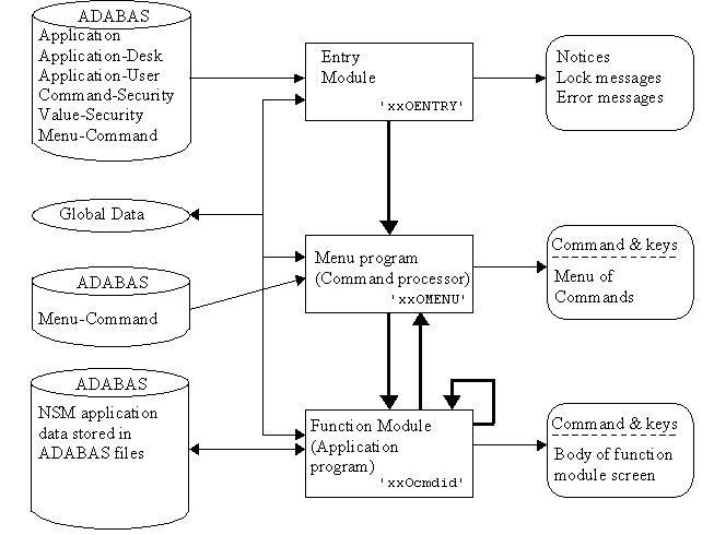
The general flow of control through all NSM v2 Architecture
systems is the same:
- The user signs onto Natural, is assigned a Desk ID, and
chooses an application to use.
- The application entry module is executed to validate the
user's access, establish the necessary control parameters, and
display any application notices the user has not yet
received.
- The menu program is executed to display menus.
- The subprogram 'NSNVCSV' is called to validate any commands
issued.
- Any valid function module is executed until another command
is issued or PF3 is pressed. Commands may be for other function
modules or for menus. When a function module command is entered
and PF2 is pressed, the current function is suspended by the use
of a
FETCH RETURN to the new function. A PF3 will return to any
suspended function or, if none, invoke the menu program and
display the menu containing the current function module
command.
This process is depicted graphically in Figure 4.
Figure 4.
Processing Flow of an NSM Application
The NSM Architecture provides several template or model
components for building a new application, all of which can be
found on the SYSTEM library. A template global data area and the
map used for menus are provided and must be installed in the new
application's library, renamed and then modified for the specific
application. The 'xx' within the names of these components is
replaced with a standard application prefix used at the
University of Arkansas. All maps and local data areas for the
individual functions must be built by the programmer, but
guidelines and models for these are also provided. This process
is described further under the heading "How
To".
The NSM Architecture depends heavily upon the global data area as
the means of maintaining profile information on the user and the
application, as an area to hold menu information in order to
minimize data base accesses, and as the means of passing key
fields from one menu or function module to other function
modules. The required global data fields for the NSM Architecture
are in the data area xxGLOBAL. This data area should be copied
for each application and modified to include the key fields and
other shared values used by the application.
This is the only map required to display an NSM application's
menus, regardless of the number of menus defined. Because most of
the menu display and processing is common for all NSM
Architecture applications, a model menu map is provided. This map
is xxMMENU and it includes a processing rule that determines the
command selected by the user. The banner of the map should be
customized to contain the key fields that are desired. Generally,
there should be no editing or validation of these key fields on
the menu map; that is the responsibility of each function module.
The menu provides these fields as a convenience to the expert
user, so that the necessary keys may be provided in advance and
an extra screen and terminal I/O avoided within the function
module.
All models developed for the NSM architecture have template local
data areas and maps stored on SYSTEM. Please see the UAF Program
Generator documentation for a current list of models and their
associated template local data areas and maps. Refer to the
section "How To" for detailed
instructions on using the maps.
The program generator is used to create the entry program, the
menu program, optionally a help program, the error program, and
the function modules. Several function module model programs have
been developed. Up-to-date information on these models can be
found in the UAF Program Generator Functional Specifications.
Each application using the NSM Architecture will have one entry
module or startup program. This program is automatically executed
whenever a user signs onto the application (a Natural Security
definition is required). This program must be unique for each
application since its primary function is to initialize the
global data area elements which are used by the NSM Architecture.
The primary functions performed by the entry module are:
- Determine if execution is being performed online or batch
and, if batch, exit the entry program.
- Set terminal control to allow lower case data on input or to
translate all lower case characters to upper case.
- Assign the error processing routine.
- Utilize a system function to identify the current user,
determine the logical application, and assign these values to
global variables for reference throughout the system. It is
useful for debugging to alter these assignments during testing in
order to simulate a different user.
- Call the subprogram 'NSNVULP2' to validate the user's/desk's
access to this application and initialize global variables
related to the application and to that user's profile parameters,
command security restrictions, and security level. Users not
authorized to access the application are requested to contact the
application administrator and are then signed back on to the
LOGON application. (All users at UAF are auto-logged into our
LOGON application. If a user has defined an application onto
which he wishes automatically logged, this step is completed for
him. Otherwise, the user will select an application to use from
the LOGON screen.)
- Read any value restrictions that are applicable and assign
them to global variables for use by the function modules.
- Initialize global application key fields as required.
- Transfer control to the menu program to display the main menu
for the application. Commands which the user is not allowed to
access are removed from the menu.
The entry module is easily generated using the Natural ISPF
edit macro PGZENTRY.
The menu program is responsible for displaying each requested
menu. When a command is requested from a menu, the subprogram
'NSNVCSV' is called to validate it, and the menu program will
fetch the valid function module, display the appropriate menu, or
provide an error message. PGZMENU is the Natural
ISPF edit macro that generates the menu program.
This program supplies application level HELP. A list of up to 14
help topics is displayed, and the user can mark any number of
topics desired. The subprogram UANSHSS is the routine called to
display the help information from the appropriate Predict
conceptual field. After a help text is shown, the user is brought
back to the HELP screen where he can then press ENTER again to
see the next marked help selection. PGZHELP
generates this program.
An error program provides a way of trapping, interpreting, and
recovering from online errors without having to code this logic
into each online program. The error program name is assigned to
the system variable *ERROR-TA by the entry program. The error
routine performs the following functions:
- Backs out the last transaction that was in process in order
to release any held records.
- Reads the parameters (stacked by the system) defining the
error.
- Determines if the error occurred prior to the main menu, in
which case no recovery is possible and the LOGON screen is
displayed.
- If recovery is possible, the command to be executed following
the display of the error information is assigned as the last menu
prior to the error.
- Calls the standard error interpretation routine, UANERRP,
with the appropriate information.
If a program includes its own ON ERROR statement, that logic will
be invoked instead of calling xxOERROR. A program can even
include an ON ERROR, check for a specific error condition, and if
the error is not one it expected it can still call xxOERROR.
However, be aware that if a program invokes subprograms or
subroutines, you will not be able to determine in which module
the error occurred. This is not a problem with an error program
since Natural stacks the name of the module where the error
occurred. PGZERROR generates this program.
The NSM Architecture utilizes several subprograms in order to
minimize the amount of code that must be maintained. These
subprograms reside on the SYSTEM library where they can be shared
by all applications. This is also very efficient since Natural is
reentrant, i.e. all users of any NSM application share the same
copy of the subprogram in the buffer pool (as of Natural V2.1.4).
This routine, modified from the original 'NSNVULP' for NSM version 2,
validates the user's access and loads necessary parameters. It is
called by the entry module when a user first signs onto an
application. It is more involved than this title indicates since
it performs all of the following:
- Reads the USER file to retrieve and translate the user's
preferred field attribute and color definitions. If no
preferences are specified, default values are assigned. The
global variable for default application is also set.
- Accesses the APPLICATION file and sets global variables for
the main menu command id, application prefix, application owner,
valid actions, minimum security levels for those actions, and the
switch identifying if modifiable fields should be protected for
those actions.
- Accesses the APPLICATION-USER file
and updates the date the application was last accessed by the
user, if necessary.
- Accesses the APPLICATION-DESK file
and the associated
COMMAND-SECURITY file in order to set variables for the user's
command security restrictions and security level.
- If the command security group or the application is locked, a
message is displayed including the reason for the lock and the
operator is sent to the LOGON application.
- If the user has never logged in, a welcome message is
displayed that includes the name of the application administrator
in case there are questions.
- If the user has not logged in since the last notice, the
notice is displayed.
- If there are any errors or inconsistencies encountered, an
error message is displayed and the operator is returned to the
LOGON application.
The subprogram NSNREADU is a utility program which takes as
input a user id, looks up the id on the USER file, and returns
the user's name in first-middle-last name sequence.
This subprogram performs the same functions as NSNREADU and also
returns the user's budgetary unit.
The subprogram 'NSNVCSV' is used to validate a command and set
command dependent variables. It is called by the menu program and
all function modules and is thus a critical part of all NSM v2
applications. This routine determines if the command id issued is
a menu or a function module, whether or not the user is allowed
to execute the command, and, if valid, the user's security level
within the command. Appropriate variables are set for each case
so that the calling program can determine if a menu should be
displayed, a function module fetched, or an error message
displayed.
All of the standard NSM v2 programs (entry, menu, and the
standard models) utilize local data areas in order to minimize
the amount of code to be maintained uniquely within each
application.
This local data area includes the common field definitions needed
by all entry programs.
This local data area includes the common field definitions needed
by all menu programs.
This local data area includes all the necessary local field
definitions required by the HELP program.
There are a few areas where copy code has been used in order to
minimize the code that must be maintained in application specific
programs.
The copy code NSCVCSV contains the call to the subprogram
'NSNVCSV' and the variables required for it.
The copy code NSCVULP2 contains the call to the subprogram
'NSNVULP2' and its required variables.
The copy code UACPFKEY should be included in each function module
prior to customizing the PF Key assignments. It will set all PF,
PA and Clear keys to be program sensitive, set all PF Key names
to blank, and, on the test system only, set the Clear key to the
terminal control command '%%.'
There are two standard help routines defined for NSM
applications. For more information, please see "UAF's Standard
Natural On-Line Help Routines."
This routine is specified as the screen help routine for the
first version of NSM. It gives the user the option of receiving
screen level help for the map being executed or definitions of
commands, menus and key fields. The application's specific screen
level help is read from Predict's extended description for that
map (the map name is passed to the help routine as a parameter).
This help routine should be specified as the screen help routine
on the "Map Settings" screen of the map editor for the NSM
Version 2 primary function module maps. The user can select help
for the specific screen of the function being executed or other
general NSM topics associated with function modules. Screen level
help is obtained from Predict's extended description for the
appropriate map.
This routine should be specified as the screen help routine on
the "Map Settings" screen of the map editor for the menu map
(xxMMENU). It provides options for receiving help information on
general NSM concepts such as menus, commands, key fields,
standard PF Key usage, definition and features of the NSM
Architecture, and reporting of problems and suggestions.
Programs may be stored on the SYSTEM library to perform common
functions for all applications. These programs may be included as
commands on the application's main menu. Two of these programs
that are applicable to all applications are identified here.
Note: The Type on the MENU-COMMAND file for
these commands must be 'U'.
This program is a simple method of implementing the terminate or
finish function. FIN is the command that must be defined on a
menu in order to invoke this routine. The program merely executes
a TERMINATE statement.
This program provides a window so that the user can specify
another application to access (logon to). It also provides
access, via PF6, to the user profile maintenance function.
There are several standards that should be followed when
developing NSM-A applications. These standards are automatically
incorporated when the program generator is used with the standard
NSM modules.
All command IDs are limited to one to four characters within the
NSM Architecture. The subprogram 'NSNVCSV' constructs the program
name to be fetched (if it is valid for the user) from the
application prefix and the command ID. The resulting program is
then fetched by the calling program. The format of program names
is xxOcccc where:
|
xx
|
The application prefix as defined on the APPLICATION file.
|
|
O
|
The UAF standard for online programs.
|
|
cccc
|
The command ID.
|
All primary function module program names must conform to this
format. A function module may fetch or call another program with
a different format name. When this is necessary, dashes can be
used as fillers and the eighth character included to identify
related modules. For example NSOU may fetch NSOU---1 to perform
some associated processing.
Map names are derived directly from the command id for the
function module. The format of map names is xxMcccc where:
|
xx
|
The application prefix as defined on the APPLICATION file.
|
|
M
|
The UAF standard for map names.
|
|
cccc
|
The command ID.
|
If the function contains more than one screen, it is required
that the map names be in the format xxMccccn, where n is the
number of the screen. If the command id is less than four
characters, the remaining characters must be filled in with
dashes ('-'). For example, for the two-screen function associated
with command U (User maintenance), the map names are: NSMU---1
and NSMU---2.
Note: Maps used for decode also can follow the format
xxMccccD, whereby the remaining positions of a
command id (if less than 4) are filled in with dashes (e.g.
NSMLAO-D is the decode map for the NSM-MS list function
LAO).
All key fields that are required by a function module should
appear as output fields in the body of the screen (below the
banner). The same fields will also be in the banner; however,
they indicate what keys will be processed next in the banner.
Below the banner, the keys indicate the record currently being
processed, or, as is the case with table and list modules, the
starting record. This should prevent any confusion regarding the
association of the data displayed with the key fields in the
banner. This situation occurs when a record is being updated and
new keys are specified in the same operation.
The key fields for a function module should be validated prior to
the execution of the input statement. The prompt displayed with
the input statement should then indicate what the user should do
next, based on the validity of those keys. Through the use of
control variables, the fields that are normally modifiable within
the body of the screen can be protected if the keys provided are
invalid or the action requested necessitates they be protected
from entry. See the section "Single Screen and
Multi-Screen Function Modules" for additional recommendations
regarding function module design.
Each application should establish its treatment of lower case
data at the time the user logs on. The entry module executes a
SET CONTROL 'L' or SET CONTROL 'U' dependent upon whether the
application needs to accept mixed case input.
The Natural message line should always contain a prompt to
indicate what the user should do next. In the case of an edit
error, the notification of the error and requested correction is
an appropriate prompt. In addition to a prompt, a confirmation of
any action just completed is to be displayed on the first line of
the map (not the message line, which may be positioned at the top
or bottom of the screen). When present, this confirmation
overlays the the program name, level, and command title. A
confirmation can indicate what records have just been added or
updated or that the current operation has just been restarted.
The confirmation and prompt fields are assigned values
conditionally based upon the program logic. Utilizing this
technique, one operation can be confirmed following a PF10 at the
same time a prompt is generated as a result of new key fields
and/or a new command being entered to initiate the next
operation. Confirmations and prompts should utilize mixed case
for readability and should not contain periods.
The labels and the fields for the required keys in the banner and
the key fields displayed directly below the banner should be
displayed intensified. All other tags and output-only fields
should be default intensity. Fields that are conditionally
protected should be default intensity when protected and
intensified otherwise.
These general characteristics may be customized by a user in
his user profile by selecting an attribute and color for fields
characterized as follows and retained in the control variable
indicated:
| Description |
Control Variable |
| Modifiable default intensity |
#MD-FA |
| Modifiable intensified |
#MI-FA |
| Conditionally protected |
#CP-FA |
| Previous value |
#PV-FA |
The user selected attribute and color designations are assigned
to global control variables by the entry program and may then be
used in maps. The standard use of these control variables in the
banner is as follows:
The required banner key fields use the control variable
#MI-FA, while the remaining key fields use #MD-FA. On the menu,
only the 'Command' field should be intensified (#MI-FA).
There are other control variables used in the standard NSM
models and are required on elements within the body of the map.
See the Program Generator Functional Specifications for further
information.
System level help can be provided for each application by
developing a HELP function module. This help facility should
include:
- An overview of the application, including its purpose and
intended audience.
- A summary of the commands available within the
application.
- Identification of the primary files used by the
application.
- A description of the help facilities.
The UAF Program Generator facility provides the method of
generating this HELP function module. xxOHELP is described in the
section "Generated Programs", and
further information on the HELP model can be found in the UAF
Program Generator Functional Specifications.
Attempts should be made to limit each function module to one
screen, but the model for multi-screen function modules will
effectively handle from one to four screens. For function modules
that do require more than one screen, separate maps are
necessary, but no other irregular changes to the model or the
generated program need to be made. The primary issue is to
not establish one screen for entry of key fields
and another to operate on the associated data. The purpose of the
banner area is to avoid this design form.
The attributes of the fields within the body of the screen are
established dynamically via control variables that are set by the
program dependent upon the situation. Additionally, PF Key names
are set based upon the circumstances and appropriateness of each
PF Key. A skeleton of a standard multi-screen function module
using this technique for traditional file maintenance is:
initialize program variables
processing-loop.
   initialize loop variable
   decide for every condition
      command-id issued
         process the command
      new keys issued
         initialize new key variables
         validate action
         access primary data base record(s)
         validate data base key fields
         set prompt
         initialize NSM and screen values and screen
           validity switches
      none (no new keys or new command)
         set next prompt
   end of decide
   conditionally set dynamic field attributes and
       perform file dependencies and auto de-codes
   conditionally set pf keys
   input using map with prompt and confirmation
       based on value of screen number requested
   Process based on PFKey
   Conditional quit and return to lower level function
end processing loop
The models used by the program generator conform to this
structure. See the functional specifications on the UAF
Program Generator for additional information.
The messages and tags on the screen should be built utilizing
both upper and lower case alphabetic characters to improve
readability. Error messages displayed on reinput should also be
in mixed case and generally should not contain periods.
All data base records should be defined with a time stamp field
that is set with each record update (system variable *TIMESTMP).
Update programs read the record, display the screen, and reread
the record prior to performing an update. This prevents ADABAS
from holding records and tying them up unnecessarily (prior to
the user committing the update via PF10). The time stamp is
checked after the reread and prior to the update to ensure that
the record has not been updated by someone else. This approach
should be used in almost all cases, but may not be appropriate if
a control record or other 'count type' information is frequently
updated by many keys (a class record where a count of students
registered is maintained, for example).
Along with the time stamp field on the application, fields should
also be defined that track the update history of a record.
TIME-OF-ENTRY, TIME-OF-UPDATE, and UPDATED-BY-USER are three
standard fields that make up an audit log. When multiple screens
can update the same record, these fields should be placed in a PE
group, where each occurrence is given a fixed value for each
screen. That occurrence is then referenced on the appropriate
screen.
Provision should be made to translate coded values which appear
on a screen and display their associated descriptions. These
descriptions are typically obtained by reading tables and must be
provided for those users that are unfamiliar with the codes.
However, this translation should only be performed upon request
or when the description is already being accessed. This reduces
the system overhead associated with these data base accesses to
those situations where required. This function can also be used
to explode an entry by displaying within a window more detail
information than could fit on the base screen. PF4 is the
standard means for making the de-code request.
Note: If using a window for de-code functions, it is standard
practice for the only valid PF-Keys to be ENTER and PF3. No
PF-Key validation rules should exist on these window maps since the
window will be closed regardless of the program attention key
pressed.
In some instances it is desirable to allow special options for
the entry of a field. A date value is a prime example since input
may be desired with or without delimiters between month, day, and
year and with a two digit or a four digit year. This capability
is provided by allowing entry into an alphanumeric equivalent
field on the screen and translating this value to the native
field format desired. This extra processing and coding is
justifiable to avoid use of the Natural edit mask on modifiable
data and to provide multiple input formats for the same data. The
edit mask is avoided because the resulting error message from
data entered in an incorrect format is cryptic and does not
indicate the format that should be used. Multiple input options
for a value are provided as a user convenience and can greatly
speed data entry when formating characters are omitted.
There are a few common considerations and standards regarding
the use of alpha equivalent
variables.
Alpha equivalent variables are defined in the global data
area's BKF group if the the corresponding native
fields are banner keys. However, if they are not banner keys,
these fields should be defined in either the MSE
or a special AEV group within a function's LDA.
Defining function specific alpha equivalent variables in the
LDA's MSE versus AEV group is
generally a matter of personnel preference; however, they cannot
be in the MSE of TARGET functions.
The alpha equivalent value displayed on the screen must match
the value of the native field and conform to a default
presentation format. This is handled in one of three ways
dependent upon whether the native variable is a banner key field,
an MSE element whose value only changes based
upon direct user input, or an MSE element whose
value may be changed by program assignments. Furthermore, due to
the suspend feature, the alpha equivalent of a banner key field
must be defined at the end of the SKS to ensure
the proper restoration of its value.
Banner key fields are often programmatically set based upon
user selections and options. In order for program assigned values
to be displayed correctly in their alpha equivalent variables,
the alpha values must be assigned before the map is presented.
This assignment normally involves MOVE EDITED
statements for each alpha equivalent variable. The standard for
these assignments is to code them in the copycode
aaCSETAE and INCLUDE this
object where required. This copycode is included in different
places dependent upon the model used.
Non-list
models:� � For a non-list model, there are two
possible situations where banner keys have been set
programmatically and in both situations
#NEW-KEYS is true. To ensure that the alpha
equivalent values are correct in these circumstances, the
INCLUDE aaCSETAE statement should be placed in
the NKRESET modifiable block. In fact, the
program generator generates this statement but leaves it
commented out.
- Next Record processing alters the keys programmatically and
sets #NEW-KEYS to true. Because only the native
value of the banner key field is assigned with the MOVE
HGV.#HIST-SEARCH-KEY TO SKS.#SEARCH-KEY and the
MOVE BY NAME SKS TO BKF, the alpha equivalent
must be assigned by the INCLUDE aaCSETAE in
NKRESET.
- When the user comes from a list where he selected an entry
that contains a banner key field with an alpha equivalent, then
the selected banner key field must have its alpha equivalent
field assigned. Since #NEW-KEYS is always set to
true upon the initial entry into a function, and the
AEV assignment must be made at this point to
handle the Next Record situation described above, the
INCLUDE aaCSETAE in NKRESET
fulfills this requirement.
An example of a non-list function with banner key
AEV fields is LVOMB in the LEAVE library.
List
models:� � For a list model, there are also two
possible situations where banner keys have been set
programmatically; however, the circumstances and solutions are
different.
- In a list model, the selection of an entry from the list
results in the movement of the list key fields to the banner, but
#NEW-KEYS is not set
to true. If any of these list keys has an alpha equivalent, that
value must be set prior to the presentation of the next screen.
The program generator for list models takes care of this
situation by including a generation variable that asks if an
AEV field for a Banner Key is included in the
LSK. If so, the INCLUDE
aaCSETAE statement is generated in the section of code
after map presentation that executes the move of the selected
entry to the banner.
- The user may enter the list function from another list where
he selected an entry that contains a banner key with an alpha
equivalent. As with non-list models, the selected banner key
field must have its alpha equivalent field assigned. Since this
situation will only occur upon the initial entry into the
function, the INCLUDE aaCSETAE should be placed
in the INIT modifiable block. The program
generator generates this statement in INIT.
For an example of a list program that contains a banner key
field that has an alpha equivalent value, see TAOLDPD in the
TARGET library.
Due to the suspend function, there is also a need to restore
the alpha equivalent value for a required banner key. On the
function to which the user suspended, he may change the value of
the AEV banner field. To ensure that the
original alpha equivalent value for that required key is restored
upon the return from the suspend, that AEV field
should be included at the end of the SKS fields
(beyond the bytes redefined as #SEARCH-KEY) in
the function's LDA. Here they will be preserved by the
MOVE BY NAME BKF TO SKS so that they may later
be restored upon the return from a suspend via the MOVE
BY NAME SKS TO BKF.
If the above steps are followed, the alpha equivalent values
displayed in the banner of all functions will always match the
native values actually being used by the programs prior to map
presentation.
MSE elements that use alpha equivalent
variables and are only altered via direct user input should be
initialized whenever the keys change. This can be done any time
after the MSE values are established. It is
recommended that the statements that initialize these variables
(MOVE EDITED or others) be placed in the
INITVAL modifiable block. From this point
forward, the alpha equivalent values will be maintained in sync
with the native values by the processing rules discussed below in
"Entry and validation".
MSE elements that use alpha equivalent
variables that are altered via program assignments require a
different solution to ensure that the alpha value displayed
always corresponds with the native value. One approach is to
reassign the alpha equivalent variable whenever the native value
assignments are performed. However, this is sometimes
accomplished in a complex routine or a protected area of code as
with the PEGM model (the EdOpt changes the native values). The
simplest solution is to place these assignments in the
PREMAP modifiable block so they are always
performed prior to the display of the map and thus always in sync
with the native values.
The values entered from the screen into alpha equivalent
variables must be edited for the correct format and the native
fields must be set to the equivalent values. This is accomplished
through the use of processing rules. Invalid entries should
result in a REINPUT with the text of this
message customized so that the proper format for the entry is
included. This processing rule should be rank
0 for all banner key fields. For banner
keys, the standard is to allow the user to exit with bad data in
the alpha field. The code should allow an exit if PF3, PF4, or
PF5 is pressed, OR 'FIN' or 'LOG' has been entered in the
#COMMAND-ID-ISSUED field but the PF-KEY is not PF10 (see UACDATEI
in SYSTEM for an example). For non-banner key fields, the rank of
this format validation and translation processing rule must be
established with consideration for how the corresponding native
field may be used in other processing rules. For example, the
native value may require further validation and may be used to
perform a de-code function. In this case two rules would be used,
both less than rank 50, and the rule that performs the alpha
equivalent format validation and translation is a lower rank than
the one performing the data base validation and de-code.
Note: Since these processing rules may be
less than rank 50 they will be executed during a view action if
PF4, de-code, is pressed. Therefore, the corresponding REINPUT
should not be performed when PF4 has been pressed.
To facilitate use of this technique, to standardize input
formats for common fields, and to maximize code reuse, several
standard copycode objects have been created to accomplish this
processing. These objects use the new Natural 2.2 feature of
providing arguments to copycode so that the alpha equivalent and
native variable names can vary with each invocation. These
include:
|
UACDATEI
|
Allows entry of a date in month-day-year format, with or
without dashes or slashes, and with a two or a four digit year.
The resulting value is always displayed as: MM/DD/YYYY. The
native field must be format D.
|
|
UACCCCIN
|
Allows entry of Company Cost Center with or without delimiting
characters and with or without the project number (last four
digits). The resulting value is displayed as: 9999
99999-99-9999.
|
|
UACSSNIN
|
Allows entry of Social Security Number with or without dashes
while displaying the result as: 999-99-9999.
|
Please see the specific code for additional information. Also
note that the last two routines accept a blank value which is
translated to a null native field value (UACDATEI requires a
parameter that determines if a blank value is allowed). When a
non-null value is required, an explicit check for a non-null
value must be provided. This can be done in the main program when
dealing with banner key fields or by adding an additional
processing rule for other fields.
The maintenance of department and budgetary unit associations
throughout our applications has presented a unique problem
because the names and associated codes (abbreviations) used to
identify these organizations commonly change. Due to this
situation, numeric identifiers for these entities were created,
and applications were designed to store the numeric identifier
rather than the code so that massive conversions would not be
required when a unit changed its name. The DEPARTMENT and
BUDGETARY-UNITS tables, where possible values reside, are keyed
by both the numeric identifier and the code. To aid the user in
data entry the convention is to allow entry of the familiar code,
translate this to the equivalent numeric identifier, and store
the numeric value on the data base. Similarly, to aid the user in
interpreting output, the numeric value from the data base should
be translated to the alphabetic code for display purposes.
The processing considerations for code translations are the
same as those for "alpha equivalent" variables previously
discussed and those standards should be applied. The difference
is in the manner of translation, rather than IF ...
MASK and MOVE EDITED statements being
used these translations require table look-ups. Two subprograms
have been developed to perform this function:
UANRDEPT and UANRBU. Given a
numeric identifier they will return the four character code and
name, or given the code (and a zero numeric identifier) they will
return the number and name. Use of these routines reduces the
need to define the necessary data base views and FIND statements,
and therefore is encouraged. To assist in the validation of alpha
codes entered online, two copy code members have been developed:
UACDEPTI and UACBUCN2. These
accept arguments for the appropriate field names for: the 4
character alpha code, the 4 digit numeric identifier, and the
name of the unit (the name is optional; see the actual copycode
for further information). (UACBUCN2 also uses a control variable
to reduce I/O by only reading the file when the code field has
actually been modified.) These should be invoked from a
processing rule on the alphabetic code field. The same guidelines
as for alpha equivalent fields regarding the rank of these rules
applies to these code translations (banner key fields should use
rank 0).
Code translations for key fields have some unique
circumstances that are not handled the same as the alpha
equivalents. The following standards have been developed to
address these situations.
- In a list model, the user may select an entry which contains
the numeric value for the alpha code in the LSK and move it to
the banner. Since the code translation occurred in the database
access in order to retrieve the alpha code that is displayed on
screen, both the numeric value and its alpha code should be
stored in the LSK. The MOVE BY NAME LSK TO BKF will then move
both values to the banner so that no further database lookups are
required.
- Code translation in a Basic Table Maintenance function (BTM
model) is similar to the AEV processing for the list model: the
code translation for banner keys should be done in the INIT
modifiable block (see the Alpha Equivalent Variables
documentation). This is because the user could have entered a
code from another function and there is no Next Record processing
nor TARGET processing in a BTM. The user, however, may press PF8
to page forward in the table of entries. When the user moves
forward, the last table entry is moved to the banner to be used
as the starting search key for the Read. If that entry includes a
numeric value that uses a code translation as a key field, then
the alpha code should also be moved along with the numeric value.
Therefore, the alpha codes also should be stored in the Table Key
Fields (TKF). The MOVE BY NAME TKF(#MAX-TBL-OCC) TO BKF ensures
that the alpha code will be moved along with the numeric value to
the banner and will be used by the Read.
- Banner key fields in a maintenance function model (MSF, TMSF,
PEGM, TPEG) can be programmatically assigned by Next Record
processing, transaction retrieval on a Review, or selection of
transactions from a list. These situations all result in only the
BKF numeric field being assigned. Since #NEW-KEYS is set to true
for all these cases, the code translation lookup can be performed
based on these conditions in the NKRESET modifiable block. For a
non-TARGET function, the necessary code is as follows:
  IF #PS-PF-NAME = 'NextR'
    CALLNAT code-translation-subprogram
  END-IF
For a TARGET function, this code should be structured as follows:
  IF (#ACTION-REQUESTED = 'R' OR TTF.TXN-SELECTED-FROM-LIST
      AND TTF.TXN-EXIST) OR #PS-PF-NAME = 'NextR'
    CALLNAT code-translation-subprogram
  END-IF
An example of code translation can be found in
NSM-MS, command LDB (List Desks for a Budgetary Unit).
The following steps describe how to develop an application
using the NSM Architecture. For references to program generation,
please consult the UAF Program Generator Functional
Specifications for detailed instructions and a list of current
models and their required components.
- Have the new application defined to Natural Security by the
Natural Administrator.
- Have your application, command security groups, value
security groups, application-users, and menus defined to the
NSM-A files through the NSM Maintenance System (NSM-MS).
- Copy the model global data area (xxGLOBAL) into the
application library and save it with the correct application
prefix. Edit the new global to contain the required banner key
fields (under the structure BKF). If the application uses value
security, the structure CAF (Common Application Fields) is used
to define the value restrictions. Stow the global data area.
- Generate the NSM-A xxOENTRY, xxOMENU, and xxOERROR programs using
PGZENTRY, PGZMENU, and PGZERROR. Make modifications that are required. The
entry module may be stowed at this point, but the menu program
requires a map. Save the menu program.
- Copy the model menu map (xxMMENU) into the application
library and save it with the proper application prefix. Edit it
to include the banner keys defined for the application. These
fields should be brought in directly from the application's
global data area so that the fields contain the proper qualifier
(BKF). Stow the map and then the menu program may also be
stowed.
- If value security will be utilized, write the value security
maintenance module to be included in the NSM Maintenance System.
This program must be defined in the Application file as the
application's value security maintenance program before users can
be assigned value security groups.
- Have your entry module defined as the STARTUP program to
Natural Security.
- A local data area is required for all function modules, and
each function module type has its own model local data area, in
addition to the one stored on SYSTEM that is required for that
module type (see "Local Data Areas").
Build an LDA from the appropriate model following the method used
for maps (see item 10).
- For each type of function module
developed, a model map has been defined and stored on SYSTEM.
Copy the appropriate model map (e.g. xxMMSF) into the application
library, save it using the new application prefix, and then
modify it to include your banner keys. At this point, it can be
saved and used as a prototype map for all the same type of
functions in your library, and the banner keys, off-screen
elements, and PFKey processing rules will already be defined. It
is desired that the banners of all maps be consistent.
- Use your prototype map of the desired model to create each
function module map. Define the fields on the map by bringing
them in from your function's local data area.
- Lastly, generate each function module, modify as required,
and test.
Using the NSM Architecture and the How To steps identified above,
it is very easy to develop a prototype of an application. The
menus are easy to create or modify and the function module
programs can be as simple or complex as desired and are easily
generated. Field validations and help facilities can be added at
any time. This provides a graduated means of developing an
application and results in a system that a user can logon to, use
and hopefully provide beneficial feedback for the development
process.
Security administration of NSM-A applications is simpler and more
timely than a centralized staff performing all administration in
Natural Security. This is accomplished by having the application
owners perform these administrative functions themselves, online,
using the NSM Maintenance System. This replaces the typical
procedure of:
- User A asks centralized security administration for access to
System B.
- Security administration refers User A to the Owner of System
B and states that written approval will be required.
- User A discusses his need with the Owner of System B.
- A memo is drafted requesting the needed access, written
approval is obtained from the Owner of System B, and the request
is sent to Security administration for processing.
- A phone call is made from Security administration to the
Owner of System B to clarify or complete the information needed
to establish the desired access.
- Security administration establishes the necessary
access.
- A phone call is made back to the Owner of System B or User A
to let them know access has been granted and that they should
test out the access privileges.
Centralized security administration is entirely removed from
this loop, and the owner immediately establishes the necessary
access for a new user or alters that access as circumstances
require. This should not be a burden since the use of the online
system is simpler and more confidential than a method of sending
memos and making phone calls. The NSM Maintenance System also
provides a record of who last made a change (See "Audit Log"), allowing some means of investigating
any disputed entries.
There are several steps involved in converting applications to
the second version of the NSM architecture. Each of the following
conversion instructions should be followed in order. For all
references to program generation, consult the UAF Program
Generator Functional Specifications for more information on that
facility.
Create a new Global Data Area as described in the section "How To", remembering to include your key
fields and value restrictions (if used). Generate the Entry and
Menu programs.
It is recommended that the programmer convert function modules in
groups of model types. The logical first step in
this process, therefore, is to determine into what model category
the programs fall. This procedure necessitates that the
programmer be familiar with the developed models.
Following the instructions in "How To"
and the program generator documentation, construct your
function's template local data area for the specific model (e.g.
xxLMSF).
The maps are constructed following the rules in the UAF Program
Generator Functional Specifications. For the conversion process,
the most efficient method to convert maps is usually to use the
old map as the foundation for the new one. In this way, the
inline field validation rules will not have to be re-typed. The
following list details the steps for conversion of maps.
- Delete the old Title field and replace with new
TITLE-AND-CONFIRMATION array field from the local data area
(stored on SYSTEM) for the particular model with which you're
dealing. It is important that this field be set up properly so
that the title and confirmation will be displayed correctly.
Define the array (".a" command) as one occurrence beginning with
#TAC-OCC. Also, put in the Dynamic Attribute parameter (DY) the
following: ^I|, which will allow the
confirmation to be displayed intensified and the command-id at
the end of the field to be displayed default intensity.
- Delete remaining banner fields and bring in new ones from the
global data area, using the BKF structure fields. Remember to put
in the proper help routines. Control variables are now used with
the banner key fields (and all these fields are Output Modifiable
-- COMMAND-ID-ISSUED used to be Input but is no longer): #MI-FA
is used as the control variable for those key fields in the
banner that are to be intensified, and #MD-FA is to be used for
those fields to be default intensity.
- Fields directly below the banner that show the user the
action and record being acted upon also need to be changed. The
Action field that was ACTION-IN-PROCESS is now
CFF.#EFFECTIVE-ACTION (included from the model's lda), and the
key fields being acted upon are now the Search Key Structure
(SKS) fields (included from your function's lda). See any of the
NSM*** maps in NSM-MS for examples.
- Delete the off-screen elements which were standard to NSM
version 1. Replace them with the standard fields for the
particular model with which you're working.
- Unlink the old PFKey processing rules, and include the new
rules for the specific model. Unlinking is accomplished by typing
'unlink' on the command line of the processing rule editor. All
standard verification rules begin with the prefix 'NS-'.
- Rules that perform decode functions should be of rank less
than 50. Likewise, validation rules that do not need to be
performed if the user presses PF4 should be of rank 51 or
greater.
- Change the qualifier (normally READ-VIEW.) to the appropriate
qualifier. For example, for MSF functions, the qualifier is MSE.
This can most easily be done by typing 'D' (Display Field
Definitions) on the main map editor menu and going through the
list and replacing READ-VIEW with the correct qualifier.
- Decode fields normally are qualified with DCF.
- Rename map names for multi-screen functions to conform to the
standard format (See "Map Name
Format").
- Ensure that the map contains all the new fields (like
CFF.#SCREEN-REQUESTED for MSF) required for the particular model
and that the necessary control variables are properly used.
After the function module's local data area and map(s) have been
created and stowed, generate the program using the appropriate
edit macro. Modify the areas that are required, and change or add
any other code needed. Finally, thoroughly test your program.